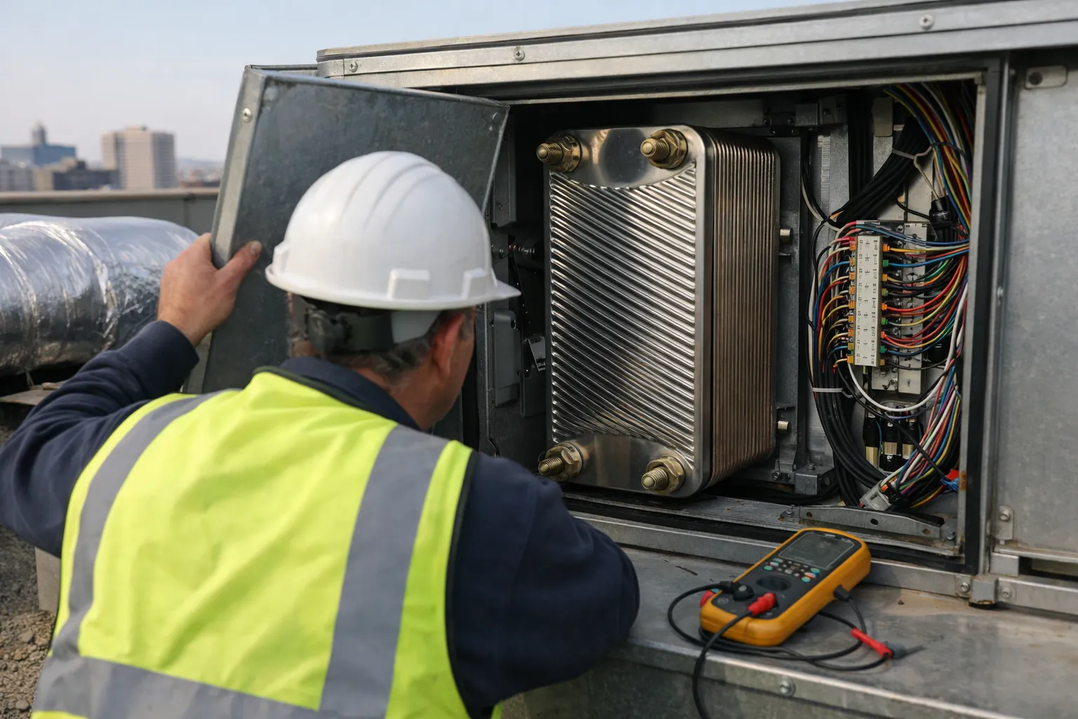
Retrofitting a packaged air-handling unit (AHU) with a cross‑flow or counter‑flow plate heat exchanger (PHE) is one of the fastest ways to cut heating (and cooling) energy while preserving indoor air quality. This guide walks through selection, mechanical integration, control sequences, frost protection, commissioning and verification—with worked examples and commissioning checkpoints HVAC enthusiasts can apply in real projects.
Why choose a plate heat exchanger?
- High sensible recovery: Plate units typically recover 50–80% of sensible heat with relatively compact footprint.
- No rotating parts: Lower maintenance vs rotary wheels; no particle carryover through moving seals.
- Low cross‑contamination risk: Properly gasketed plate units can be specified to meet leak limits and are easier to purge/clean than wheels.
- Compatibility: Works with existing duct geometry and filters, and can be configured for enthalpy core (moisture transfer) if required.
When to use plate vs alternatives
- Plate PHE — Best for cold climates where sensible recovery matters and when cross‑contamination must be minimized. Good for retrofit into limited depth AHUs.
- Enthalpy wheels — Higher total energy recovery (sensible + latent) and smaller pressure drop, but risk of carryover and wheel maintenance.
- Run‑around glycol loops — Good when face‑to‑face location inside unit is impossible; more complex with pumps and freeze protection.
- Heat pipes — Passive, low maintenance, limited effectiveness vs plates for large temperature lifts.
Key design inputs
- Design airflow (CFM)
- Outside air and return air design temperatures and relative humidity
- Required recovery type: sensible only or enthalpy (latent + sensible)
- Allowable pressure drop (in. w.g.) and available fan horsepower
- Access and duct geometry for insertion/retrofit
- Material compatibility (aluminum, stainless, polymer) for outdoor exposure or corrosive environments
Sizing and recovery effectiveness
Use this common engineering relation for sensible heat recovery (BTU/hr):
Q = 1.08 × CFM × ΔT × η
Where ΔT = (return temp − outdoor temp) and η = recovery effectiveness (decimal).
Worked example (realistic retrofit scenario):
- AHU Outside Air = 10,000 CFM
- Return air = 70°F, Outdoor design = 30°F → ΔT = 40°F
- Plate exchanger effectiveness = 0.65 (65%)
Q = 1.08 × 10,000 × 40 × 0.65 = 280,800 BTU/hr ≈ 82.3 kW sensible heat recovered.
Fan power penalty
Plate cores create pressure drop. Approximate electrical penalty: convert CFM to m³/s and inches w.g. to Pa.
CFM to m³/s: multiply by 0.00047195. 10,000 CFM ≈ 4.72 m³/s. 0.5 in w.g. ≈ 125 Pa.
Fan power (kW) ≈ (flow_m³/s × ΔP_Pa) / (fan_efficiency × 1000)
If ΔP = 0.5 in w.g. (125 Pa) and fan efficiency = 60%:
Power ≈ (4.72 × 125) / (0.60 × 1000) ≈ 0.98 kW.
Net effect here: ~82.3 kW heating equivalent recovered vs ~1 kW electrical penalty for fans—usually an attractive tradeoff.
Mechanical integration checklist
- Confirm footprint, orientation and direction of flow. Counter‑flow offers higher effectiveness for a given face area.
- Provide access doors and service clearances per manufacturer recommendations (filter/plate cleaning access).
- Ensure gasket seals and frame flanges are compatible with existing casing. Re‑seal all joints to avoid bypass leakage.
- Include bypass damper and blanking capability for summer or maintenance. Bypass must be motorized and interlocked with controls.
- Provide condensate drainage for outdoor cores or when enthalpy (moisture) transfer is active.
- Support structure for weight and vibration isolation if required (especially rooftop installs).
Frost protection strategies
In cold climates plate cores can frost on the outdoor air side. Common approaches:
- Outdoor air preheat coil — Hot water, steam or electric preheat upstream of the PHE to keep core surface above freezing.
- Recirculation/bypass — Close OA damper, open return bypass to recirculate warm return air across core until outdoor conditions are safe.
- Glycol Run‑Around Loop — Move heat from exhaust to outdoor air side with antifreeze; keeps core frost-free but adds pumps and freeze protection complexity.
- Control logic — Use outdoor temperature, outdoor dew point, and core differential temperature to trigger frost protection.
Practical control rule: enable heat recovery only when outdoor dry‑bulb > freeze threshold OR core outlet temp > 32–35°F. For humid outdoor air, consider enthalpy effects and monitor humidity sensors to avoid moisture problems.
Controls and BAS integration
Robust control reduces frost events, prevents IAQ issues and maximizes savings. Implement the following signals and interlocks:
- OA damper, RA damper, supply fan and exhaust fan statuses
- Core bypass damper position
- Temperature sensors: OA inlet, RA inlet, OA outlet (post‑core), RA outlet (post‑core)
- Core ΔT sensor (RA_out − OA_out) for performance monitoring
- Optional: differential pressure across core (detects blockage), VOC sensor or fast CO2 sensor for cross‑contamination alarm
Typical control sequence (simplified)
- If economizer conditions satisfy free cooling, evaluate whether recovery should be bypassed (avoid overcooling supply).
- Monitor OA_temp & OA_dewpoint. If OA_temp > frost_setpoint OR core_out_temp > 35°F, enable recovery (close bypass).
- If frost risk detected (OA_temp below setpoint and core_onset ΔT reducing), initiate frost sequence: open bypass and/or run preheat coil; if preheat is available, stage it before bypass.
- Lock out recovery during any detected cross‑contamination alarm (VOC rise, differential pressure reversal) and notify maintenance.
Commissioning and verification
Commissioning should demonstrate mechanical integrity, control performance and measured energy benefits. Follow these steps:
- Document pre‑retrofit baseline: metered gas/electric for the AHU, supply temperatures and airflow measurements for a minimum representative period.
- Static leakage and smoke testing: with both dampers closed, use a smoke pencil across plate seams and gaskets to find bypass leaks.
- Airflows: verify design CFM on OA and total supply. Adjust dampers and fans to meet design and record face velocities (target 300–500 fpm for most plate cores; confirm with vendor).
- Temperature runs: with recovery enabled, record OA_in, RA_in, OA_out (post‑core) and RA_out (post‑core) stable readings. Compute measured effectiveness: η_meas = (T_RAin − T_OAout) / (T_RAin − T_OAin).
- Pressure drop: measure core ΔP and compare to design; log impact on fan power.
- Frost sequence: simulate design cold/humid conditions or use staged logic to verify preheat/bypass operation and that control returns to normal after thaw.
- Cross‑contamination/trace testing: for critical IAQ projects, perform tracer gas testing using helium or approved non‑odorous tracers (obey local regulations). Alternatively, use high‑sensitivity VOC sensors to detect leakage over time. Avoid SF6 due to GWP concerns.
Acceptance metrics
- Measured effectiveness within ±10% of specified value
- OA and RA airflow within ±10% of design
- Core leakage below manufacturer spec and no observable smoke bypass
- Frost cycle works within target outdoor temp range with no sustained supply temperature violations
- Documented energy savings and simple payback estimate using metered data or modeled savings validated by short‑term monitoring
Maintenance recommendations
- Inspect and clean plates annually (frequency depends on particulate load). Remove and pressure‑wash per manufacturer instructions.
- Check gasket condition and replace if flattened or brittle.
- Verify drain lines and condensate pans for enthalpy cores; keep traps and drain lines clear.
- Monitor core ΔP; rising ΔP indicates fouling or blocked filters upstream.
- Log frost cycle events and cross‑contamination alarms in BAS trending.
Simple payback example
Using the worked example above (10,000 CFM, 82.3 kW recovered):
- Hourly heat saved ≈ 82.3 kW → 280,800 BTU/hr
- Assume a heating system efficiency of 90% and natural gas price of $12 per MMBtu (adjust to local rates).
- Useful gas saved per hour ≈ 280,800 BTU / 0.90 ≈ 312,000 BTU/hr ≈ 0.312 MMBtu/hr → $3.74/hr at $12/MMBtu.
- Annual hours (heating season) use reasonable estimate (e.g., 1,800–2,000 hours). At 1,800 hours saving ≈ $6,732/yr.
- Subtract incremental fan electricity: 1 kW × 1,800 hr × $0.12/kWh ≈ $216. Net annual savings ≈ $6,516.
If installed cost (equipment + labor + controls) is $40,000, simple payback ≈ 6–7 years in this scenario. Adjust energy prices, hours, and incentives for accurate project economics.
Regulatory and IAQ considerations
Check local code and ASHRAE 90.1 requirements—heat recovery is mandatory in some climate zones for certain applications. For healthcare or laboratory spaces, additional cross‑contamination controls and alarm requirements apply. When specifying enthalpy cores, confirm resistance to mold and appropriate filtration upstream.
Practical checklist before leaving the site
- Temperature and airflow readings recorded and saved to BAS.
- Frost protection sequence verified at the commissioning setpoints.
- Bypass damper travel limits and interlocks set and tested.
- Maintenance access and procedures left with facilities staff, including spare gaskets and cleaning schedule.
- Alarm thresholds set for core ΔT, ΔP and VOC/Cross‑contamination.
Plate heat recovery retrofits deliver significant energy savings for AHUs when properly sized, integrated and commissioned. For HVAC enthusiasts and pros alike, the technical payoff is greatest when careful attention is paid to controls, frost protection and verified performance. Start with accurate airflow and thermal surveys, engage a reputable core vendor early, and require BAS trending and acceptance testing to lock in the savings.