Introduction
This updated September 2026 guide shows HVAC technicians, contractors and system integrators how to diagnose and mitigate two linked failure modes increasingly seen after retrofits to low‑global‑warming‑potential (low‑GWP) refrigerants: oil migration that starves compressors, and short‑cycling that both accelerates wear and drives oil out of the crankcase. You will get an actionable, field‑tested workflow, updated tool lists (including IoT and oil‑sensing options introduced in 2024–2026), concrete fixes, and commissioning tests that reflect OEM and industry service guidance released through mid‑2026.
Who this is for: practicing HVAC technicians, commissioning teams, plant engineers, and service managers responsible for equipment retrofitted to A2L refrigerants (e.g., R‑454B), R‑1234yf blends, and modern HFO/zeotropic mixtures.
Prerequisites and context — what’s changed through 2026
Since the wave of retrofits beginning in 2024, OEM technical bulletins and field service networks have consistently flagged oil migration and short‑cycling as among the top post‑retrofit service calls. Two trends matter for diagnostic strategy in 2026:
- Wider adoption of A2L and HFO blends across rooftop, commercial refrigeration and light industrial applications, bringing increased emphasis on oil management and flammability‑aware service practices.
- New field tools and connectivity: low‑cost wireless temperature/pressure loggers, oil‑level sensors for crankcases, and cloud analytics have become commonly available for field diagnosis and post‑repair verification.
Technician prerequisites: EPA/region‑equivalent refrigerant handling certification, familiarity with ASHRAE 15 (or local code) for mildly flammable refrigerants, and OEM‑specific retrofit service bulletins for the compressor and refrigerant in use.
Tools and instrumentation you’ll need (updated)
- Multichannel data logger or BMS access with timestamped compressor run/on‑off events and thermostat calls (48–72 hour minimum capture).
- Digital manifold gauges (calibrated) and surface/immersion temperature probes for accurate superheat/subcooling measurements.
- Clamp ammeter and high‑resolution power meter capable of capturing inrush and running amps with 100 ms resolution.
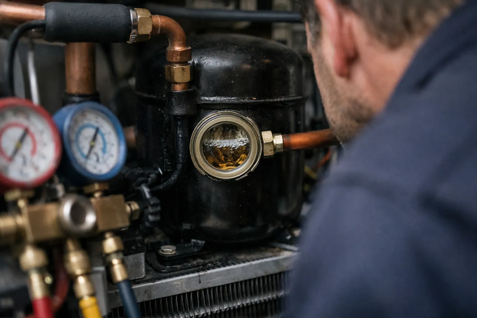
- Crankcase oil sight glass or sampling port, plus clear tubing for visual checks; portable oil sampling kits for field lab submission.
- Wireless crankcase oil‑level sensors (float or capacitance type) — now widely available for retrofit monitoring and automated alarms.
- Refrigerant identifier / sniffers that detect A2L species and concentration; ultrasonic leak detector for locating leaks.
- Infrared camera / surface thermometers for diagnosing oil blankets on evaporators/expansion devices; vibration sensor for compressor health.
- Portable vacuum pump, recovery equipment and flushing kit (performed only by certified personnel).
Field diagnostic workflow — step by step (updated for 2026)
1. Establish baseline, safety and paperwork
- Confirm certifications and PPE for A2L/flamable refrigerant service. Verify gas detection and ventilation are in place per ASHRAE 15 and local code.
- Collect system history: retrofit date, OEM retrofit kit used, oil type and charge records, prior compressor or separator installs, and any OEM service bulletins applied.
- Record exact symptom timeline: shortest observed on/off cycles, time of day, external loads (e.g., door openings on a grocery case), and any logged protective trips (low‑oil, high‑temp).
2. Capture runtime and cycling data (use connected monitoring when available)
- Record compressor on/off events, thermostat calls and fault bits for 72 hours. Use cloud logging if the site has an IoT gateway to preserve data for OEM escalation.
- Flag rapid cycling: on/off intervals shorter than 5 minutes are high‑risk; for systems with new refrigerants, consider a 5–10 minute minimum run time for staging or BAS logic.
- Correlate cycles with electrical patterns and load (door sensors, freezer defrosts, business hours) to determine whether cycles are demand‑driven or protective trips.
3. Visual inspection and mechanical checks
- Inspect filter driers, suction accumulators, sight glasses and liquid lines for oil stains or pooling. Note exact locations (evaporator outlet, receiver inlet, drier body) and photograph for records.
- Check piping slopes, long horizontal runs, and line sizes against manufacturer guidance for the specific refrigerant/oil pair — improper slopes remain a top cause of oil retention.
- Confirm crankcase heater (or crankcase heat management) operation and timer settings. In 2026 many OEMs recommend thermostatically controlled heaters or controlled via BAS rather than simple power‑on timers.
4. Measure pressures, temperatures and charge indicators
- Record high/low pressures and corresponding saturation temperatures; calculate subcooling and superheat at recommended measurement points.
- Interpretation updates: high evaporator superheat with near‑normal subcooling frequently points to oil coating on the TXV/expansion device or reduced evaporator effectiveness from oil films. Low subcooling often indicates undercharge or receiver/accumulator oil accumulation.
- Document liquid line temperatures and flash gas signs—some low‑GWP blends show different heading behavior that affects oil‑refrigerant separation zones.
5. Compressor startup, oil return and inrush tests
- Perform an extended run test: run the compressor under normal load for several hours and log amps, oil sight glass status, and suction superheat changes. Modern field experience shows oil return sometimes requires 2–6 hours of stable operation to clear pooled oil.
- Measure starting and running amps; repeated high starting currents after long off periods are consistent with oil pooling or low crankcase oil height.
- If available, use wireless oil‑level sensor data to confirm oil accumulation/return during the extended run. If oil sampling is practical, send samples for viscosity, acid number (AN), and metal particle analysis.
6. Targeted component checks and retrofit hardware audit
- Expansion device: inspect for oil coating; confirm superheat control and consider replacing orifices/TXVs per OEM low‑GWP retrofit kits if metering is impaired.
- Oil separator: verify differential pressure and that return lines are unobstructed. Some 2025–2026 service kits include thermostatic oil return valves sized for specific refrigerant/oil pairs.
- Suction accumulators and traps: confirm sizing, placement and presence of oil drains or traps installed at low points. Accumulators are being re‑sized in many retrofits to match lower oil‑carrying tendencies of some blends.
Common root causes and fixes (with 2026 refinements)
Below are typical root causes and practical fixes validated by OEM technical letters and large service networks through mid‑2026.
1. Wrong oil or contaminated oil
Cause: Using non‑OEM or mixed lubricants (mineral/POE/PAG) increases oil solubility changes and promotes migration.
Fix: Replace with OEM‑specified lubricant. After contamination or during retrofit, perform a controlled flush (follow OEM approved procedures) and sample oil after 300–500 operating hours to confirm stability.
2. Poor piping geometry or insufficient oil return velocity
Cause: Long horizontals, incorrect slopes, and oversized suction lines reduce oil return.
Fix: Add oil traps at low points, correct slopes, or install an oil separator sized for the compressor and refrigerant. When re‑piping is impractical, choose an oil separator with a thermostatic or timed return matched to the oil type.
3. Crankcase cooling and heater strategy
Cause: Crankcase heaters that are off during frequent cycling or not thermostatically controlled allow refrigerant to condense and displace oil.
Fix: Use thermostatic crankcase heaters or BAS‑controlled heaters that follow OEM guidance. In high‑cycle systems, consider controlled pre‑heating before start or continuous low‑power heat during long low‑load periods.
4. Short‑cycling from control logic or protective trips
Cause: Incorrect staging, aggressive fault logic, or sensor placement causing premature shutoffs.
Fix: Implement minimum run timers (5–10 minutes for many packaged units), refine deadbands, and tune PID control loops. For inverter or VFD‑driven compressors, configure soft‑start and avoid full stop/start sequences for small load swings.
5. Undercharge and leaks
Cause: Low charge impairs oil transport and raises suction superheat, prompting cycle variations.
Fix: Conduct a leak survey, repair and recover/recharge per OEM charge tables. Verify subcooling at full and part load.
When to add hardware: practical guidance in 2026
Hardware additions are more common in 2025–2026 retrofit projects than they were during early pilots. Consider these when piping and controls cannot fully fix the problem:
- Oil separators sized for your compressor and refrigerant; prefer separators with thermostatic return valves to avoid over‑returning oil during low ambient periods.
- Timed oil return pumps on large systems with long vertical lifts—these actively move oil back on a schedule and are proving effective in supermarket rooftop banks.
- Suction accumulators that are correctly sized for the refrigerant’s oil carry‑over characteristics; many retrofits require larger accumulators than the original HFC design.
- Smart BAS logic with oil management commands (minimum run, oil return cycles, crankcase heater control) and integrated oil‑level alarms.
Always validate new hardware compatibility with the refrigerant/oil pair and consult OEM service bulletins released during 2024–2026.
Commissioning verification and acceptance tests (updated checklist)
- Baseline capture: compare 72‑hour pre‑ and post‑repair cycling counts and run durations using logged data.
- Thermal performance: verify subcooling and superheat at near‑design and a part‑load point; record steady‑state after at least 2–6 hours of stable run for oil return confirmation.
- Oil condition: document sight glass condition, oil‑level sensor readings, and oil lab results (viscosity, AN, metals) where available.
- Electrical: record start and running amps; note reductions in inrush and stable running amps as evidence of recovered lubrication.
- Report and handoff: include photos, annotated pressure/temperature logs, and any BAS logic changes. Set recurring alerts in CMMS for cycle counts and oil alarms.
Maintenance best practices to prevent recurrence (practical, 2026)
- Adopt periodic oil analysis after retrofit: initial sample at ~500 hours and then annually or per OEM recommendation; increase frequency in high‑cycle sites.
- Log compressor run hours, cycle counts and oil‑level sensor trends in CMMS; set automated alerts for sudden rises in cycle rate or oil‑level drops.
- Inspect filter driers, sight glasses and accumulators at each planned maintenance visit; replace driers after any major repair or contamination event.
- Keep OEM firmware and control logic current; many OEMs released low‑GWP‑specific software updates in 2024–2026 addressing soft‑start and oil management.
- Train service teams annually on refrigerant‑oil chemistry differences and safe handling practices for A2L refrigerants, and maintain current competency certificates.
Updated case examples (2025–2026 field context)
Example 1 — Supermarket chain (Midwest, retrofit 2025): After converting a rooftop pack to R‑454B, the site experienced repeated 3–4 minute cycles and low‑oil trips. Diagnosis found an inoperable crankcase heater, oil pooling in a downstream filter drier, and no oil separator. Actions: repaired heater, replaced oil with OEM POE, installed a thermostatic oil separator and updated BAS minimum run to 8 minutes. Result: stable multi‑hour runs, normalized amp profile, and no further low‑oil trips in 12 months of monitoring.
Example 2 — Data center CRAC units (pilot retrofit 2026): Three units retrofitted to a low‑GWP HFO blend showed high evaporator superheat and gradual performance loss. Wireless oil‑level sensors indicated intermittent oil drainback during night cycles. Solution: piping rework to add suction traps and a timed oil return pump on the riser. Post‑work telemetry showed restored heat transfer and stable control temperatures.
When to escalate to OEM or consider compressor replacement
Escalate when oil analysis shows high acid number, metal particles, or when logs indicate irreversible mechanical damage (bearing noise, scoring, persistent high amps after extended run). Provide OEM with complete logs (pressures, temps, amps, oil lab) — OEMs can often determine whether a servicekit or replacement is required, and whether warranty applies.
Common mistakes to avoid
- Assuming legacy HFC practices translate directly to A2L/HFO retrofits — oil chemistry and refrigerant behavior differ.
- Failing to capture continuous run/cycle telemetry before making piping changes—lack of baseline undermines verification.
- Mixing lubricants during service without full flush; partial flushing often worsens miscibility problems.
- Relying solely on sight glass color without oil sampling or sensor verification in cold‑start conditions.
Pro tips
- Use wireless oil‑level sensors during initial 1,000 hours post‑retrofit to catch transient migration events; tag alarms into CMMS for automated dispatch.
- For inverter/VFD‑driven systems, prefer soft‑stop/soft‑start and speed modulation rather than full motor shutdown to limit oil separation events.
- When installing an oil separator, size it based on compressor displacement and expected oil carryover for the specific refrigerant; consult OEM separator selection charts.
- Keep a “post‑retrofit folder” on site: OEM bulletins, oil MSDS, lab results, and a compact run‑cycle log for the first 90 days after retrofit.
FAQ
How often should I perform oil analysis after a low‑GWP retrofit?
Initial oil sample at roughly 300–500 operating hours after retrofit (sooner if symptoms occur), then annually if results are stable. Increase frequency (every 3–6 months) for high‑cycle or large systems until 1,000–2,000 hours provide a stable baseline.
Are oil separators always compatible with A2L refrigerants?
Most modern oil separators are compatible, but you must verify the separator’s internal media and thermostatic return valve against the specific refrigerant/oil pair. Use OEM selection charts and confirm rated working pressures and return‑temperature behavior for the blend in use.
Can software or BAS tuning alone fix oil migration problems?
Control changes (minimum run timers, soft‑start) can significantly reduce short‑cycling and improve oil return, but they rarely solve mechanical piping issues or wrong oil types. Use controls as the first and reversible step, then pair with piping/hardware fixes if issues persist.
What oil‑level alarm thresholds should trigger action?
Set alarms for rapid drops in oil level (>10–20% loss within 24 hours) and for persistent low levels below manufacturer minimum. Combine low‑level alarms with cycle‑rate alerts to prioritize dispatch.
When is compressor replacement the only option?
If oil analysis shows heavy metallic debris, very high acid number, or if bearings/internal components exhibit irreversible wear despite proper oil and refrigerant management, replacement is often the most reliable route. Provide full logs to OEM to confirm diagnosis and warranty options.
Resources and next steps
- Consult OEM technical bulletins for your compressor and the refrigerant used (check updates through 2026).
- Review ASHRAE safety guidance for A2L refrigerants and local code requirements for flammable refrigerants.
- Consider short trials of wireless oil sensors and cloud logging during future retrofits to build an evidence base for your fleet.
Oil migration and short‑cycling remain high‑value diagnostics in 2026: a methodical combination of updated telemetry, targeted mechanical corrections, compatible hardware (separators/pumps), and refined BAS logic will resolve most issues without major asset replacement. Keep detailed logs, use oil analysis to guide decisions, and work with OEM support when signs point to mechanical damage.