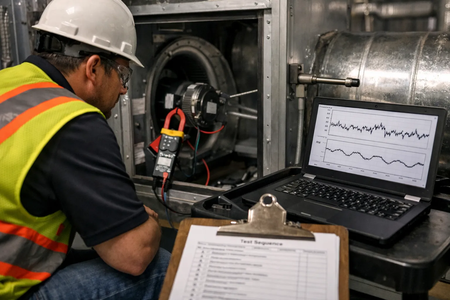
This guide walks HVAC enthusiasts and field technicians through a repeatable, standards-informed process to verify variable-speed electronically commutated motor (ECM) fan retrofits on large air handling units (AHUs). It focuses on in-field measurements, test sequences, analysis, and practical acceptance criteria so you can confirm energy savings, airflow performance, and control integrity after an ECM or VFD+ECM retrofit.
Why verification matters
ECM retrofits promise significant fan-energy reductions, but real-world savings depend on correct sizing, controls, duct resistance, and commissioning. Poor measurement or incomplete testing can mask problems such as improper drive tuning, air leakage, control conflicts, or unintended changes to system airflow that compromise comfort or ventilation rates. A methodical field verification process documents what the retrofit delivered and provides action items for remediation.
Scope and prerequisites
- This guide is aimed at large AHUs (single fans >5 hp or systems serving multiple floors), and assumes the retrofit replaced a constant-speed PSC or older induction motor with an ECM or ECM + VFD arrangement.
- Follow site safety procedures and isolate power when accessing rotating equipment.
- Consult applicable standards for formal test methods: AMCA (fan performance) and ASHRAE guidance for airflow testing and commissioning. Use AMCA 210-style traversing techniques for accuracy where possible.
Tools and instrumentation
- Multi-channel power meter (true RMS) measuring line voltage, current, power, and power factor for the fan motor or VFD input/output.
- Portable data logger or laptop with BACnet/Modbus access to VFD/BAS variables (speed command, frequency, motor current, kW, suction/discharge pressures).
- Tachometer (non-contact) or encoder access (for shaft speed verification).
- Pitot tube and differential manometer (traverse kit) or hot-wire/thermal anemometer (with traverse grid) for duct/section airflow; or calibrated flow hood for small diffusers (not suitable for large ducts).
- Static pressure probes and manometers to measure external static pressure (ESP), fan inlet and outlet static pressures, and filter differential pressure.
- Thermometers/hygrometers to log supply and return air temperatures.
- Belt tachometer and tension measurement tools if belt-driven fans remain.
- Calibration sheets and calibration stickers for instruments.
Pre-test checklist
- Document AHU ID, location, motor nameplate, pre-retrofit motor power (if available), fan wheel diameter, pulley sizes (if belt drive), ductwork layout, and design CFM.
- Confirm controls: is the ECM operating as a direct-replacement ECM (internal controller) or under external VFD/BACnet speed commands? Note the control source and available telemetry.
- Verify filters and dampers are in expected state (new/clean filters, isolation dampers open). Record filter differential pressure.
- Stabilize system: run with normal airflow setpoint and allow 10–15 minutes for temperatures and speeds to steady before measurements.
Test sequence — step-by-step
Run the following sequence to capture the fan performance across the operating range.
1. Baseline documentation
- Capture current steady-state at normal operating speed: motor voltage, current, kW, power factor, shaft speed (RPM or Hz), inlet and outlet static, filter DP, supply temperature, and return temperature.
- Log BAS/VFD reported kW and motor frequency if available.
- Measure airflow at a representative duct cross-section using a traverse per AMCA 211 principles. Record CFM and uncertainty estimates.
2. Multi-point testing
To verify the fan curve and ECM behavior, test at 3–5 speed levels: e.g., 100% (normal), 75%, 50%, and minimum running speed (or lowest commanded). At each point:
- Allow stabilization (3–5 minutes) after speed change.
- Record kW, line volts, amps, PF, RPM/frequency, supply/return temps, inlet/outlet static pressures, and flow traverse data.
- If the system operates with variable geometry (VAV boxes modulating), temporarily set terminal boxes to full open or select an AHU serving a stable zone to isolate fan testing. Coordinate occupant impacts with facility staff.
3. Fan power verification
Measure motor input power directly with the power meter. For VFD-driven ECMs, record both VFD input and motor output where possible. Compare measured kW against BAS-reported kW for discrepancy analysis.
4. Speed vs. flow curve
Using the multi-point data, plot fan speed (Hz or RPM) vs measured airflow, and fan power vs airflow. For a direct-drive centrifugal fan without major system changes, fan laws predict:
- CFM ∝ speed
- Pressure ∝ speed^2
- Power ∝ speed^3
Significant deviations suggest altered system resistance, controller limits, or measurement error.
5. Verification of control behavior
- Command step changes from the BAS or VFD and confirm the ECM responds smoothly (no hunting or oscillation). Record transient behavior with a data logger if possible.
- Confirm minimum safe speed and stall protection features are functioning; record motor temperature and current during extended low-speed operation.
Calculations and example
Example: AHU measured at 100%: 20,000 CFM, measured motor input = 18.0 kW, RPM=900. At 75% speed command, measured CFM=15,000, measured kW=9.6 kW.
- Expected power scaling from fan laws: power_75 ≈ power_100 × (0.75)^3 = 18.0 × 0.422 = 7.6 kW. Measured 9.6 kW indicates higher-than-expected power—investigate causes (VFD losses, motor inefficiency, higher system pressure).
- CFM scaling: expected CFM_75 = 20,000 × 0.75 = 15,000 CFM (matches measurement).
When measured power exceeds fan-law expectation by >10–15%, common causes include:
- VFD inefficiency or harmonics causing higher input power readings;
- ECM internal control / torque characteristics that deviate from ideal cubic behavior;
- Added pressure drops upstream/downstream (dampers, filters); verify filter DP.
Acceptance criteria (practical)
Define acceptance criteria before testing. Example acceptance criteria for an ECM retrofit might be:
- Airflow at normal operating point within ±7% of design or pre-retrofit verified CFM (unless the retrofit explicitly changed setpoints).
- Measured motor input kW reduction at normal operating point ≥30% relative to pre-retrofit baseline (or project-specified target). If no baseline exists, use expected performance from vendor datasheet with documented corrections.
- Measured kW vs airflow curve follows fan-law trend within ±15% across tested points; deviations require root-cause analysis.
- BAS-reported kW within ±10% of measured kW; larger discrepancies must be corrected (metering calibration, BACnet mapping).
- No hunting or oscillation during step-response tests; speed settles within specified time (e.g., 10–30 seconds) without overshoot exceeding 5% of setpoint.
Common troubleshooting checks
- High measured power at low speeds: check VFD carrier frequency, motor cooling (insufficient cooling at low speed raises motor losses), and bearing drag.
- Lower-than-expected airflow at high speed: inspect inlet/discharge obstructions, dampers, or unexpected damper commands in BAS.
- Discrepancy between BAS kW and field meter: verify CT/PT sizing and wiring, check integration math in BAS for transform ratios.
- Vibration or noise changes: examine wheel balance, verify wheel orientation and set screws after retrofit.
Reporting and documentation
A robust verification report should include:
- Project and AHU identification, dates, and personnel.
- Pre- and post-retrofit documentation and any nameplate changes.
- Instrumentation details and calibration dates.
- Tabulated multi-point measurement data (speed, CFM, static pressures, kW, volts, amps, PF).
- Plots of speed vs CFM and CFM vs power with fan-law overlay and percent deviation.
- Clear pass/fail statements against acceptance criteria and prioritized corrective actions if needed.
- Photographs of sensor locations, meter hookups, and label changes.
Practical tips and gotchas
- Traverse placement: perform traverses at straight-run sections per standard recommendations. Avoid bends, diffusers, or locations with strong asymmetry where possible.
- Filter condition matters: always record filter DP and, if possible, test with a representative clean filter to isolate motor performance from increased system resistance.
- Motor cooling: ECMs often have internal electronics that are cooled by airflow. Running an ECM too slowly for long durations can increase motor temp and change efficiency—note motor temperature during low-speed tests.
- Communication latency: if using BAS commands, account for communication delays that may cause apparent control instability during step tests.
- Uncommanded compressor staging or simultaneous central plant interactions can skew AHU measurements—coordinate with facility operations.
When to escalate
Escalate to vendor support or an engineer when you find:
- Measured power consistently deviates from expected curves and basic checks (filters, dampers, VFD settings) are clear.
- Control instability that risks comfort or equipment life.
- Significant airflow loss that cannot be explained by field conditions (damper failure, blocked coils, incorrect pulley ratio).
Closing: documenting value and continuous improvement
Field verification converts vendor promises into documented performance. For building owners and energy managers, a completed verification substantiates savings, supports incentive claims, and identifies tuning opportunities. For technicians and enthusiasts, mastering these measurements builds confidence and reveals the subtle interactions between motors, drives, controls, and building systems. Use the test data to refine control schedules, adjust minimum speeds, or recommend ductwork fixes — each measured improvement compounds the energy and comfort gains from an ECM retrofit.