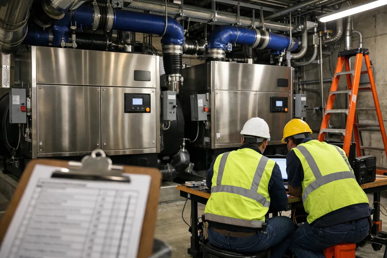
Magnetic‑bearing (oil‑free) centrifugal chillers — commonly sold under lines such as Turbocor/Danfoss and by major OEMs as their magnetic‑bearing models — are increasingly selected for projects demanding high part‑load efficiency, low maintenance and oil‑handling elimination. This field guide walks HVAC enthusiasts and technicians through the entire practical process of specifying, preparing a site, commissioning, and validating performance for magnetic‑bearing chillers in 2026 projects.
Why choose magnetic‑bearing chillers now?
Magnetic‑bearing chillers use active magnetic bearings and direct‑drive variable‑speed compressors to eliminate oil systems and improve part‑load performance. In today’s environment — tighter energy codes, growing electrification targets and utility incentives — their advantages often include:
- Higher part‑load efficiency and stronger seasonal performance than many screw or older centrifugal designs.
- No oil charge or oil filtration systems, reducing oil‑related maintenance and environmental risk.
- Compact packages with variable‑speed capability for better modulation and reduced short‑cycling.
- Lower vibration and quieter operation in many installations, useful for retrofit and downtown sites.
When a magnetic‑bearing chiller is the right choice
Assess the technology against these project conditions:
- High annual operating hours or significant part‑load hours (office buildings with long operating seasons, hospitals, data centers with chilled water cooling, campus central plants).
- Desire to reduce onsite oil handling and simplify maintenance regimes.
- Space constraints or need for modular redundancy (magnetic‑bearing chillers are available in smaller unit sizes that can be paralleled).
- Ability to meet upfront incremental capital costs (they carry a price premium versus basic screw chillers; check incentives).
Specification checklist (what to ask for)
When writing or reviewing specifications, include firm technical and contractual items:
- Manufacturer and model family; include certified performance maps (AHRI or manufacturer‑published) with part‑load points.
- Full‑load and part‑load kW/ton (or COP) at typical site conditions (e.g., 44/54°F, 32/85°F entering conditions) and multiple part‑load points (25%, 50%, 75%).
- Minimum turndown ratio and stable operation envelope (minimum flow, turndown in % of nameplate capacity).
- Site power requirements: nominal voltage, full‑load amps, starting characteristics, recommended generator sizing and harmonic mitigation needs.
- Control interfaces: BACnet/IP and/or Modbus TCP, available I/O points, alarm schemes and trending capabilities.
- Vibration and sound specifications, factory testing (FAT) options and warranty details for bearings/inverters.
- Shipping weight, lifting points, required rigging/crane capacity and unit footprint (including service clearance).
Site preparation and constraints
Magnetic‑bearing chillers have specific site needs that must be addressed before equipment arrival.
Structural and rigging
- Verify floor loading or rooftop curb design. Provide manufacturer’s certified weight and lifting point locations early in the schedule.
- Plan for crane capacity, spreader bars and temporary rigging. Some units are modular but still heavy — don’t assume fit‑through doors.
Mechanical/hydronic
- Maintain recommended minimum chilled‑water flow and ΔT to keep the compressor in its stable operating envelope. Magnetic‑bearing compressors are sensitive to low‑flow, low‑load conditions.
- Include isolation valves, flexible connectors and spring‑supported piping to avoid transmitting pipe strain to the chiller base.
- Pipes should be flushed and chemically treated per manufacturer directions prior to startup — debris and scale can damage internal heat exchangers.
Electrical and power quality
- Confirm service voltage tolerance, sequence, and availability of a separate disconnect. Magnetic‑bearing chillers use power electronics and require stable input.
- Discuss power factor correction and harmonic mitigation. Many units include active front ends; nevertheless utility interconnection requirements or generator compatibility should be verified.
- Coordinate with electrical contractor on grounding, surge protection and the location of VFD/drive panels relative to the chiller.
Controls and building automation integration
Successful integration makes or breaks operational savings.
- Specify BACnet/IP as the baseline protocol and request a device object list (BIBBs supported). If the site BMS is older, include Modbus RTU/TCP as a fallback.
- Define control sequences for lead/lag, setpoint reset, CHW pump control and fault response. Magnetic‑bearing chillers rely on smooth modulation — avoid aggressive setpoint jumps and poor pump control strategies that induce short cycling.
- Require access to controller trend logs and a remote support channel (secure VPN or OEM cloud) for the first year of operation for tuning assistance.
Commissioning: step‑by‑step
The commissioning process for magnetic‑bearing chillers combines mechanical checks with specific electrical and vibration verifications.
- Pre‑startup review — Confirm piping, insulation, make‑up water, chemical treatment and cleared strain. Ensure power wiring and grounding are complete.
- Factory Acceptance Test (FAT) review — If a FAT was performed, review reports and verify serial numbers and control software revision.
- Cold mechanical checks — Valve orientation, strain relief, shaft clearances if provided, emergency shutdown functionality and alarm wiring.
- Power checks — Verify voltage, phase rotation, neutral and ground. Energize control power and verify communication with BMS.
- Rotor lift and bearing autotest — Magnetic bearings actively lift the rotor at startup. Follow manufacturer procedures for initial spin‑up, monitoring bearing currents and lift confirmation. This is a critical step — do not bypass safety interlocks.
- Vibration baseline — Record vibration levels (in mm/s or ips) at startup and at several load points. Establish baseline values for trend comparison.
- Performance verification — Run the chiller at several part‑load points and measure kW, chilled‑water flow and ΔT to calculate kW/ton. Compare to manufacturer maps and contract performance guarantees.
- Control tuning — Adjust lead/lag algorithms, flow control and setpoint resets. Recheck for hunting and stability over several diurnal cycles.
- Final documentation — Compile test reports, as‑left sequences, calibration certificates for sensors, and operator training records.
Acceptance tests and key metrics
Make acceptance conditional on documented test results:
- kW/ton measured at specified chilled/heating water temperatures and at least three load points (25%, 50%, 100%).
- Vibration and bearing temperature within manufacturer limits.
- Successful transition between lead/lag and test of fault recovery (e.g., simulated loss of chilled water flow or high suction pressure).
- Verified BMS object list, alarm propagation and trending capability.
Maintenance and common troubleshooting
Maintenance differs from oil‑lubricated machines:
- No oil filters or oil change procedures, but expect regular vibration monitoring and periodic checks of bearing currents and inverter cooling systems.
- Air filters, condenser cleanliness and water treatment remain critical. Fouled heat exchangers reduce suction pressure and can push the compressor outside its stable range.
- Power quality events (brownouts, transients) can stress power electronics; ensure adequate surge protection and plan for UPS/backup per site criticality.
Retrofit considerations
Replacing a legacy screw or older centrifugal chiller with magnetic‑bearing technology requires careful systems thinking:
- Check building chilled‑water ΔT strategy. Many buildings run low ΔT and rely on larger flows; magnetic‑bearing units often perform best with higher ΔT and sufficient ΔP across coils.
- Assess existing hydronic plant capacity, pump control and expansion tank sizing. You may need rewiring of controls and new piping headers for parallel operation.
- Plan for staged commissioning and temporary cooling or plant downtime if replacing lead units in a multichiller plant.
Economics: quick example calculation
Use a conservative, transparent worked example to set expectations. This is illustrative — run project‑specific numbers before decisions.
Assumptions:
- Plant size: 400 tons equivalent
- Annual full‑equivalent operating hours: 2,000
- Baseline average annual energy intensity (existing screw chiller): 0.60 kW/ton
- Magnetic‑bearing projected average annual intensity: 0.45 kW/ton (25% energy reduction — manufacturer‑reported, site dependent)
- Electricity price: $0.10/kWh
- Incremental installed cost vs. baseline: $150,000
Annual baseline energy = 400 tons × 2,000 hrs × 0.60 kW/ton = 480,000 kWh
Annual new energy = 400 × 2,000 × 0.45 = 360,000 kWh
Annual savings = 120,000 kWh = $12,000/yr
Simple payback = $150,000 / $12,000 ≈ 12.5 years (before incentives)
Notes: Incentives, demand charge reduction, maintenance savings and avoided oil handling risk can materially shorten payback. Conversely, different operating hours or electricity rates will change outcomes.
Common pitfalls and how to avoid them
- Insufficient flow or ΔT assumptions — confirm hydronic strategy early and model plant operation across seasons.
- Poor power coordination — engage the electrical contractor and utility early to evaluate harmonics, inrush and generator compatibility.
- Skipping FAT or field factory tests — insist on manufacturer test reports and, where practical, witness tests on critical machines.
- Poor BMS integration — require the device object list in the contract and perform BMS integration testing during commissioning.
Final checklist before project approval
- Performance maps and AHRI/manufacturer certification supplied and contractually guaranteed.
- Detailed rigging and weight drawings provided; structural sign‑off complete.
- Electrical service confirmed, grounding and surge protection specified.
- Hydronic flow, pump controls and ΔT strategy designed and simulated.
- Commissioning plan and factory/field test schedule included in contract.
- Operator training and one year of remote monitoring or OEM support included.
Magnetic‑bearing chillers are a strong option in 2026 for projects where part‑load performance, low oil maintenance and quieter operation matter. They require careful front‑end coordination — electrical, structural and hydronic — and a disciplined commissioning approach that emphasizes rotor/bearing behavior, power quality and accurate performance validation. With the right specification and site prep, they can deliver lasting operational savings and lower lifecycle risk in many central‑plant applications.